
Introduction
Simple to use and able to send signals over large distances the 4..20mA current output sensors have long been standard in the industry. Most commonly used for measuring pressure and temperature but available in countless varieties they are a widespread and very useful tool.
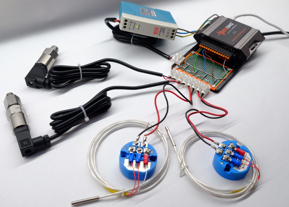
Since the sensors output current while most microcontrollers can only directly measure voltage this has left some users wondering how they should be connected to the MonoDAQ-U-X device and this is exactly what this guide is going to tackle.
Theory
Measuring current with the MonoDAQ-U-X
The U-X does have two internal shunts for direct current measurements but they are primarily intended for power measurement as demonstrated in this application note and further explained in this manual.
For measuring the signal from multiple 4..20 mA sensors we recommend using external current-measuring resistors (shunts) and use the U-X to measure the voltage drop over the shunts. Since their resistance is known the current can be calculated from the voltage drop using Ohms law.
For the best results, we want to use the 1V voltage range on the U-X. Using Ohm’s law the ideal resistor value is calculated to be 50 Ohm since the sensor’s maximum current output of 20mA will result in a 1V voltage drop over the shunt allowing us to utilize the full measuring range.
While a 50 Ohm resistor is ideal other values can also be used as long as the sensor current range will produce a voltage drop compatible with the selected voltage input on the U-X.
And remember that the current measurement will be only as accurate as the resistor resistance tolerance (unless you plan on calibrating the sensor) so precision resistors should be used. We used a 50 Ohm, 0.1%, 125mW resistor.
Types of sensors
Before we get started wiring things up we need to identify what kind of sensor we are working with. Generally, you will encounter 2-wire, 3-wire, and 4-wire sensors. Each has benefits and drawbacks but all can be used with the U-X.
If you are not sure what kind of sensor you are dealing with make sure to consult its datasheet.
Powering your sensor
Another important consideration you need to make is how will the sensor be powered. The U-X has an integrated power supply (PSU) that can supply up to 200mA of current up to a power of 1W.
Different sensors require different amounts of power but generally speaking one or two can be powered from the internal PSU. If you want to connect more sensors (a maximum of 8 sensors can be monitored with a single U-X) you will need to use an external PSU.
Caution! Make sure to account for the fact that most sensors draw more current/power as they approach the top of their measurement range
Electrical circuit
So how do we wire things up?
The most important part is to figure out which wire is the current output of your sensor. This wire is usually called the signal line and is where the variable current signal will be flowing. The shunt should therefore always be connected in line with the current output wire of the sensor.
2-wire sensor

The sensor is powered with the integrated PSU in the U-X. The voltage drop over the shunt is being measured using a differential voltage input on pins 1 and 2 (V1+ and V1-).
3-wire sensor
If we used a 3-wire instead of a 2 wire sensor not much would change. Unlike 2-wire sensors, the signal and GND are “split” into two wires.

The signal part of the circuit remains identical the only difference being an additional POWER- wire which we would connect to GND.
This configuration of a 3-wire sensor is the most widespread configuration in industrial applications.
4-wire sensor

Finally, 4-wire sensors have a separate (isolated) signal loop and power loop. Be careful when wiring signal wires of 4-wire sensors to ensure current flows in the right direction otherwise negative values will be measured
Multiple sensors
We can add more sensors by using the same logic as above. Let’s take a look at using two 3-wire sensors

At first glance, it might look complicated but don’t worry! The POWER+ and COMMON wires of both sensors are just connected together. As for the signal wire, all we did was add another shunt and wired it in the exact same way as the first one, using pins 3 and 4 (V3+ and V3-) as a differential voltage input.
But we can do even better!
Notice how V1-, V3-, and GND are (assuming resistance of wires is negligible) all on the same potential. We can simply remove V1- and V3- and use single-ended measurements (GND being the reference) to get the voltage drops on the shunts:

We have just saved 2 pins! Having one side of all shunts used connected together and tied to GND is the most efficient way of connecting sensors to the U-X.
Just keep in mind that in the schematic above the wires connecting GND and the shunts should be kept short to avoid errors caused by a voltage drop in the wire due to its resistance
External PSU
Finally, since this method is great for using multiple sensors we should really be using an external PSU to make sure there is enough power for everything.
Right now the sensors get power from the wires connected to EXT and GND. All we need to do is connect those two wires to an external PSU instead

As we mentioned the wires powering the sensors were moved from the U-X to the PSU. Notice that there is now a new green wire going from U-X GND to the common terminals of the shunts. No current flows over this wire. It is just there to establish the reference for the single-ended measurements.
This is the best way of connecting multiple sensors. It allows us to connect up to 8 current output sensors to the U-X.
Software configuration – Dewesoft X3
Channel setup
We will be using a 10bar, 2-wire pressure sensor and a 50 Ohm shunt for this demonstration. It is wired exactly like the 2-wire sensor example above.
All of the hardware has been set up so all that’s left to do is configure the X3 software to get the measured values.
The channel setup for a single sensor with pin 1 being used as a single-ended voltage measurement on the shunt should look like:

The EXC pin is set to a 24V excitation to provide power to the sensor
Math
Deriving the equations
The voltage drop over the shunt needs to be converted into whatever value our sensor is measuring. We need to find a mathematical function that will calculate this conversion.
First, we calculate the current from the shunt voltage drop that we are measuring.
I = U / R
In our case R=50 Ohm, and we want the current in mA to make further calculations easier so we multiply everything by 1000 and obtain:
I [mA] = U [V] / 50 Ohm * 1000
After the current has been calculated it needs to be converted into the value which the sensor is actually measuring.
For most sensors, the 4-20mA output range is linearly proportional to the quantity the sensor is measuring. 4mA and 20mA being the lowest and highest values the sensor can measure.
Since we are using a 10 bar pressure sensor 4mA will correspond to 0 bar and 20mA to 10bar (relative pressure). To map the current values to their corresponding pressure values the following equation is used:
p [bar] = (I [mA] – 4 mA) / 16 mA * 10 bar
The first part of the equation takes takes in the 4 mA to 20 mA current range and scales it to a value between 0 and 1. This value is then multiplied by the maximum value the sensor can measure to give us the actual pressure we are measuring.
Combining the two equations gives us the direct conversion from measured voltage to pressure:
p [bar] = ((U [V] / 50 Ohm * 1000 ) – 4 mA) / 16 mA * 10 bar
Skipping the units and simplifying the expression reveals that this is a simple linear relation:
p [bar] = U [V] * 12.5 – 2.5
Implementing the equations
We have our equations and now need to implement them in X3. This can be achieved in two different ways.
As long as the sensor has a linear output the best and most efficient approach is using the scale and offsets columns in the MonoDAQ U-X plugin tab.
Since our sensor does have a linear output this is the way to go. Taking a look at the final equation from the derivation above:
p [bar] = U [V] * 12.5 – 2.5
We input the coefficients form the final equation into the scale and offset columns.

Make sure to add the units and name the column and that’s it! The measured value is calculated immediately and can easily be visualized in the measured tab.
This way no additional memory is used up by storing unnecessary intermediate products and the number of variables is kept to a minimum keeping everything neater
Using the math tab
Alternatively, if the intermediate products are of interest and need to be stored or if the sensor’s output is not linear custom equations can be added in the math tab
This way all the values can be kept separate allowing for more complex relations to be implemented.
If for example, we wanted current and pressure to be stored separately we could first add the current equation by using the formula feature in the math tab.

And similarly, add another formula for the pressure calculation

While this approach is great for more complex measuring setups just keep in mind that the stored files will take up more space.
Filter
When we are interested in a slow-moving signal, say 50 Hz, we can set the sample rate of the MonoDAQ-U-X analog channels to 100 S/s.
But if we require a higher sample rate of the analog channels due to the requirement of other measurement channels, we can also apply a low pass filter in the Dewesoft Math section.
Using a low pass filter is a good idea if you are not intending on measuring rapid changes or oscillations. We are using a pressure sensor to monitor slow pressure changes and are more interested in precise measurements than fast changes.
A low pass filter with a 50 Hz cutoff frequency was used to smooth out the output.

Under the input filed (top left) both Current and Pressure were selected.
While current is just an intermediate value used to calculate pressure we will be displaying both just to verify the current-to-pressure function is working as we intended.
Displaying the measurement
Finally, we head over to the measure tab and set up our user interface. We add a recorder and a couple of displays and set them to show us the values we are interested in.

Looks like the sensor and our setup is working great!
Conclusion
While sensors come in many types and variations you should now be well equipped to find the right configuration which suits your needs.
If you want to learn more about practical applications of what we learned and see a real-life use case make sure to check out this use case (coming soon!) where 4..20mA sensors were used to investigate leaks in 3D printed parts.